


Stephen Mantz of Zed Audio; Interview
- Colin Miller

- Feb 7
- 15 min read
Updated: Mar 3
“While I understand it is somewhat caricature, there is something beautiful and true in the elegance and majesty of a biomechanically masterful swing.”
-Unknown
Table of Contents
Introduction:
I got connected to Stephen Mantz of Zed Audio by Ken Kreisel, co-founder of the original, Made in the USA Miller and Kreisel Sound Corporation. I needed for some repair work on some M&K MPS-2525P active speakers, part of a set of my long time favorites based on the MPS-2510P/S-150P front speaker setups. I had previously sent the pair to a different electronics repair establishment, twice, who failed to figure out some low level distortion behavior that had developed in both speakers after over two decades of reliable use. Ken said that Stephen would be the guy, since he not only did service, but had made those amplifiers for M&K.

REALLY? My attention had been hooked, hauled on deck, and served on plate.
To me, that is a pretty significant endorsement. I made the leap into fully active loudspeaker systems with the M&K MPS-2510P/2525P system, jumping in from the perspective of the equivalent passive MPS-2510s and S-85s backed up by an Aragon 8008bb and 8008x3, some of my favorite power amplifiers, ever. I have never regretted that move, in part, because the amplifier performance in those speakers are money.

Since that introduction, we have had several phone conversations about a variety of topics regarding amplifiers and the kind of work he does, and he’s always been generous with his time.
On top of repairing almost anything, even at times when original parts are no longer available, Stephen has designed and built amplifiers for quite a long time, both in car audio and high-end home audio, some of those devices being very high-end, both in performance and cost.
Those M&K amps were very much not his first rodeo. While a variety of economic factors has moved mass production of electronics largely offshore from the United States, there has been plenty of demand for repair of classic amplifiers, new ‘cost-no-object’ amplifiers for customers who want more than the mass market can or will address, or even overhauling vintage amplifiers to the point of largely gutting them and implementing Stephen’s own designs. I’ve had him revamp two Phase Linear 400 series 2 power amplifiers using his ‘Triple Darlington’ special sauce. I won’t pretend to understand the nuts and bolts of what makes it what it is, but I will say, I like it, a lot. His unassuming ‘Vintage Revamps’ are among my power amplifier favorites.
His website has a lot of general information on amplifiers and electronics. My questions may expand upon that content, but in an effort to reduce redundancy, do not entirely cover what he has already disclosed. I recommend reading it.

After I read it, I had still questions and I thought maybe others would be interested in reading the answers provided by Stephen, proposed the idea of making a Q&A public, Stephen said ‘sure’, and here we are.
The following is my best attempt at formatting our exchange in a way that is both clear, excises byproducts of my own tangential rambling, but still true to the conversation.
Stephen Mantz of Zed Audio; Interview
The Interview with Stephen Mantz, of Zed Audio.
Colin:
I wrote down a whole pile of notes, taken after reading your website papers, and I’ll get to that, in order, but I think where I wanted to start was with that Oscilloscope picture you showed me of the Hafler amp with the lateral MOSFETSs that had that weird oscillation through what seemed to be the ‘crossover’ region when driving 4 ohms, even though it was fine with 8 ohms.

I don’t have the comprehension of electronics to understand why that happens, but it’s definitely an eye-opening moment. The published specifications are fine, it has cousins using the same circuit topology that measured relatively well in publications like Stereophile, and yet I can also imagine that you could get better ‘looking’ measurements, even at 4 ohms, if you danced around it the right way. Your measurements also support anecdotal experience by myself and my friends, in that the amplifier family sounded subjectively more transparent, more ‘at ease’, less ‘fluffy’, when driving higher impedance ‘easier’ loads.
And such instances where manufacturers publish impressive specifications and yet fail miserably under conditions undisclosed, are not unique. Audio Science Review measured a Behringer amplifier, and measured the onset of clipping at 404 watts versus a 900 watt per channel rating at 4 ohms. What was also interesting is at 20 Hz, that Behringer amplifier measured by Audio Science Review began clipping at 268 watts versus the 900 watt rating.
So, I’m trying to actually narrow this down to a question, but with context so… my questions on this are…
What kind of mechanisms contribute to such anomalies, such as the Hafler Oscillation in the ‘crossover’, or lower power output at 20 Hz than 1 kHz, and what other mechanisms are there that can contribute to ‘weird’ measurements, where it may look good in one context, but perform poorly in another?
What is going on where clearly defective or under-performing products can be on the market, and they aren’t hauled into court by some regulatory committee for fraudulent products?
Are manufacturer specifications ANY indication of product capabilities? And how does any of this relate to real world performance, where you have dynamic signals (content) driving dynamic loads (loudspeakers)?
Stephen:
Behringer like all companies who copy other designs, BS their specifications as the average client has no clue.
The Transnova circuit design is in my humble opinion rife for instability due to its high open loop gain and the use of MOSFETs in the output stage. MOSFETs are orders of magnitude faster than bi-polar transistors (My choice for active devices) and so they are prone to oscillation.
Lower output at 20Hz is simply a function of power supply design because the duty cycle at 20Hz is much greater than at 1KHz.
FTC is supposed to control this but like ALL government agencies they have their heads up their a$$holes. Example when I brought my BMW 735i with me to the USA in 1983, the federal agency wanted to remove my anti lock breaking because it was illegal in the USA at that time - go figure. No they did leave it intact.
Specifications are an indication of performance but do not always tell the whole story.
Colin:
In terms of the duty cycle, is this related to pulling current from a single rail for a more extended time versus alternating quickly between two? Would this hypothetically be different if the output was balanced or ‘bridged’?
Stephen:
The duty cycle of a 20Hz vs 1KHz is much greater. Therefore the energy it takes from the power supply at 20Hz is so much greater than at 1KHz.
Colin:
Sorry if I'm being dense, but.... 20 Hz being a lower frequency, as a longer period (which I am assuming is what duty cycle means), so it makes sense that each cycle requires more energy, though a 1 kHz cycle, being much shorter, fits more cycles into a given time frame (smaller bites, but more of them). It would seem, from a simplistic standpoint, that based on that alone, 1 watt at 1 kHz would require the same power as 1 watt at 20 Hz.
And yet, that doesn't seem to describe real behavior, so obviously there's more to it than that. But something that might play at least part in that discrepancy is that a 20 Hz cycle, spending more time on one 'side' of the voltage swing than another, is going to be relying on the respective + or – rail, or just half of the total power supply, for extended periods of time. I don't know if that's right or wrong, but put that way, it makes sense to me. Is that at all related to what you're saying?
Stephen:
Incorrect. The capacitors in the power supply with a 60Hz mains frequency are refreshed to full charge value (1.414 x the AC input voltage to the rectifiers and ignoring the the rectifier's 1v approx. volt drop) at a rate of 8.3msec. So a signal at 20Hz in the amplifier itself, the time is now 50msec and at 1Khz it is 0.5 msec. So with a simple unregulated power supply the hold up time for the power supply capacitors is mainly dependent on how large the power transformers is and the value of the capacitors.
Colin:
On the topic of looking at measurements and specifications, can you give general recommendations on what somebody should look for, in terms of relevant information, indications that it might be reliable, and what kind of tests would you actually run, if you wanted to get a comprehensive idea of how well an amplifier would perform with a given loudspeaker? Do you think there are aspects of a power amplifier that are difficult to measure on standardized loads?
Stephen:
I measure these parameters: Power into loads of 2, 4 and 8 ohms at all frequencies. I am not that interested whether an amplifier can deliver full power at 20 kHz as this is not required in the real world as High frequency drivers are so much more efficient then woofers. Frequency response at 1 watt in to 2,4, and 8 ohm loads also at higher power levels, Phase response, Noise, Damping factor 20Hz - 20KHz at 2,4, and 8 ohm loads and I also use a high reactive load board I designed to see how well the amplifier behaves into this nasty load.
Colin:
You do both repairs for a lot of different amps. On the topic of repairs, I know that electrolytic capacitors will age over time and degrade. I would assume that it impacts performance over time, though if the degradation were gradual, it may not be obvious.
What kind of performance degradation do you usually see as the various capacitors in an amplifier gradually diminish, and how would that be subjectively noticed by a listener, and under what conditions?
Stephen:
Muddy sound and lack of bass response.
Colin:
The most recent amplifier I sent to you, you discovered that it was unstable under certain conditions, did your best to get it working as well as the design would allow, but there were inherent limitations related to stability on certain load ranges.
Is it rare to find amplifiers that behave weirdly, exhibiting behavior not indicated by specifications, or is it more common than many people might assume?
Stephen:
Fosgate junk!
Colin:
I read on your website that some of the 'skateboard' digital amplifiers…
Stephen:
No such thing as a digital amplifier. Class D amps are pure analog.
Colin:
Sorry, I should have said ‘switching’… Are they either not repairable, or you can try but you can't guarantee, nor will you warrantee operation?
Stephen:
Correct
CoIin:
Is this reflective of most modern switching amplifiers, or just particular amplifier designs?
Stephen:
Chinese/Brazilian junk
Colin:
Do you often find that an amplifier, in your best judgment, simply isn't worth fixing? And if so, how hard is it to convey to clients that they should punt and just buy something else?
Stephen:
Rarely.
Colin:
In terms of diminished or insufficient storage/filter capacitance in the power supply degrading bass reproduction, how would this most often show up in measurements?
Stephen:
When running a 20Hz square wave you see tilt on the scope.
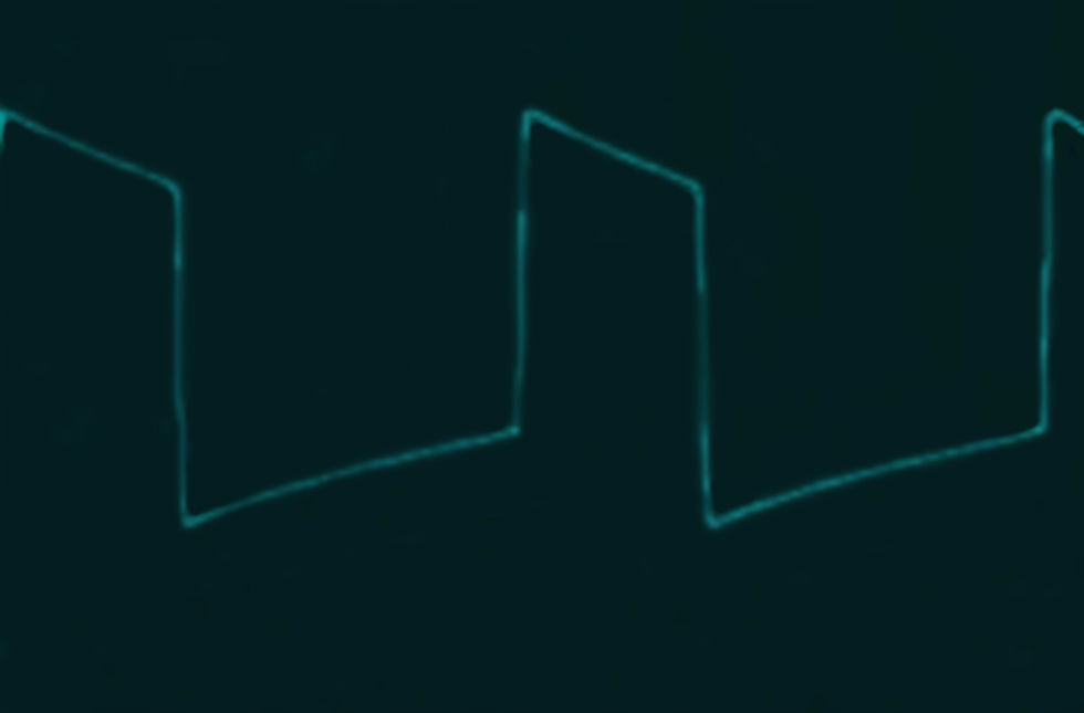
Colin:
Ah, that makes sense. That would seem to imply that the voltage sag in the power supply can impact the output even below the clipping threshold, and that corrective feedback circuits cannot correct out of a saggy power supply. Would that be a fair statement?
It also and pulls together observations I've heard from other professionals in the field. Way back James D. Johnston, who did audio-related research for AT&T among other stuff, made mention of 'gain shift' in power amplifiers as a potentially audible behavior that could be measured, but rarely if ever actually is.
Cody Hiebert, of Harbottle Audio, who makes some pretty high-end subwoofers, had mentioned that he has seen evidence of what he called 'compression behavior' in power amplifiers, related to what he called 'rail pumping', something also never mentioned in the mainstream discussion of power amplifiers.
Do these observations sound like they might be describing the same thing?
Stephen:
Yes.
Colin:
If you didn’t roll your own, what would you look for in a power amplifier in terms of specifications or measured behavior to actually assure fidelity in playback when driving real loudspeakers?
What kinds of circumstances would make sense for a customer to ask you to build them a custom amplifier from the ground up, as opposed to choosing from comparatively mass market options built with relatively economy of scale?
Stephen:
Flat response to 100KHz within 2dB
Soft clipping
Low noise floor, at least 100dB below rated output
THD less than 0.1% 20Hz-20KHz
The ability to drive lots of current = big power supply (switching supply even better), lots of output devices depending of course on the rated power. Example the amps I build, the 1.5Kw has 96 output transistors and a 6Kw power supply, the 750w/ch version has 48 output transistors per channel and a 3Kw power supply per channel.
I essentially do this when I work on Phase Linear, McIntosh, Marantz and Dynaco. The chassis remains intact as custom metal work is stupid expensive and I use my designs for the internals.
Colin:
In your design preferences, you specified switch mode power supplies, and bipolar transistors. Can you elaborate why in terms of advantages over other popular alternatives?
Stephen:
Switchmode supplies are more efficient, offer the ability to control current flow, offer regulation especially when a PFC front end is employed, smaller and substantially lighter in weight. My 3Kw transformers I use weigh in at less than 0.23Kg where a 3Kw copper + iron toroid weighs about 23Kg.
Bipolars are used in 99.99% of all amplifiers for home use because they sound better than MOSFETs, they do not need the massive idle current which MOSFETs require for low THD. They are much easier to match than MOSFETs and so in manufacturing we need a smaller batch purchase to get usable parts with bipolars. MOSFETs are more expensive and hard to find. Advantage goes to MOSFETs in speed and that they do not suffer from secondary breakdown.
Colin:
Looking up bipolar transistor 'secondary breakdown' on the interwebs, that seems like it is related to excessive current beyond the transistor rating causing localized heating and making it behave 'wonky', such that thermal runaway and catastrophic failure can result, hence the requirements to safeguard against that with protective circuits. Is that a fair layman's summary?
Stephen:
Yes.
Colin:
In amplifier designs that switch rail voltage, or vary it (such as a 'tracking downconverter'), are there any potential implications in this, or other possible unintended consequences, in designs that intentionally vary the rail voltage for whatever reasons?
Stephen:
Class H & G offer a nice solution to heat issues and efficiency but are expensive to employ as separate bridge rectifiers and filter caps are required. A buck inverter is good, complex but offers significant advantages to G & H types.
Colin:
I had a conversation in which somebody wondered if switching amplifiers (specifically some cheaper 'pro' amplifiers designed primarily for PA use) could overcome limits in rail voltage and actually 'step up' the available input voltage. I didn't know for a fact that it's impossible, so I wanted to ask somebody who might actually know, that best resource being you.
Do amplifiers that use switching outputs, or for that matter any particular topology, have an advantage in compensating or rejecting fluctuations in rail voltage provided by the power supply?
Stephen:
Class D amplifiers are more prone to "rail pumping” than class A & B when used in half bridge applications. Easy to overcome by using lots of rail capacitance and/or regulated power supply.
Colin:
When you say 'half bridge', does that mean one active 'side', and the other a ground, or 'unbridged' in common parlance?
Stephen:
Yes
Colin:
In that conversation, another wondered if some switching output Class D devices, in conjunction with the output filter, could actually step up the voltage from the rail itself. I pass on the question to you.
Stephen:
No.
Colin:
On the topic of Switch Mode power supplies, I generally understand what you're saying about the advantages in being able to implement a degree of compensation for AC mains power line sags, as well as the size/cost advantages of using higher frequency transformers that are both less expensive and take up less space and weight, all good.
Somebody had said that because they switch at a higher frequency, they charge the voltage rail filter capacitors more often, and as such, don't need near as much filter capacitance as a 'linear' conventional power supply that charges at a frequency twice the AC Mains frequency (assuming 'bridge' rectification).
Thinking about it, it would seem that if this was true, it would require some kind of significant energy storage mechanism, as the AC mains frequency will still impart regular spans of time where the available voltage is closer to zero than peak voltage. Can you clear this up?
Stephen:
The capacitors are ONLY charged at the peak of each sine wave and this is why we require large caps. In a switcher, which is typically a square wave we charge at the full duty cycle, there are several issues.
A simple off line switcher has two sets of capacitors, the first which sit after the bridge rectifier and these are charged at 120x/second. Then there are the secondary side capacitors which are charged at 2x the switching supply's frequency. So we then still rely on the primary caps to be large in value for a decent hold up time.
When we employ a PFC front end we do not have a large capacitor on the primary side after the bridge rectifier. This is typically 1-3 mF depending on the power of the PFC. The post PFC capacitors are then charged at the rate of the PFC's switching frequency but they also determine the ripple on the output of the PFC.
Colin:
You mentioned that 'half bridge' Class D switching outputs may need more filter capacitance to avoid bus pumping, but as it relates to the power supply method, do switch mode power supplies differ from 'linear' power supplies in terms of how much filter capacitance is recommended for a particular load?
Stephen:
Yes
Colin:
And, do you have any general rules of thumb as far as how much filter capacitance is considered adequate given the variables (possibly) of power supply type, power output, and load impedance?
Stephen:
No they are calculated by fixed formulas.
Colin:
Kind of unrelated side question, on the coolness idea of buying a Phase Linear 400 series, does it matter which generation?
Stephen:
I do a lot of restoration the Phase Linear amplifiers. Series II are easier to work with as they have level controls and the LED meters do not encroach so much into the chassis. I have designed my own fully complementary PCBs which utilize a series output stage for much greater safe operating area (SOA). I am in fact busy on a series II now.
Colin:
Thank you for participating in this Q&A Stephen. I look forward to the Phase Linear Series 2 amps returning, Fully Zedified.
Final Thoughts
I could have gone on asking questions, and I’m sure Stephen would have patiently answered, for a while. But it became apparent to me that the deeper we go, the more I lack the specific understanding of electronics, the real deep knowledge, to make efficient use of Stephen’s time, and at some point I would be asking questions without benefit. For a meaningful increase in understanding, I need to do the work of design, building, evaluating, and trouble-shooting power amplifier operation on a circuit and component level. I don’t think Stephen is looking for an apprentice, and at this point in my life, I don’t think that’d be the most sensible career move. Writing, systems programming, and being a wrestling coach are my sweet spot. My family and home are my priority, just like 95% of you reading this.
The workings of power amplifiers, in the real world, with real loudspeakers, with real content, as it relates to human hearing is almost absurdly complex. Actually, no, it is absurdly complex. My conversations with Stephen cleared up some extremely salient points for me, making sense of observations and the disconnect between the claims of the ‘watts are watts so long as frequency response is flat’ crowd, without resorting to the mystical pseudo technical jargon of the ‘audiophile’ cult. But as questions lead to questions, and I dug deeper looking into things like the variety of circuits used by switch mode power supplies that implement power factor correction, it became apparent that if I keep going, my universe would explode. There is just so much to these invisible forces of chain reactions.
I’ve read introductory electronics textbooks, had conversations with many audio engineers, played on the DIY front for decades. I work in a field that requires low level electronics diagnostics and fabrication, and have a pretty decent surface level understanding of what goes on in terms of everything that has to do with the laws of both Watt and Ohm.
Watts, Volts, Amps, Ohms, I get it.
Inductance, capacitance, resistance, I get it.
Reactance as it relates to phase shift, phase margin, bandwidth gain products, corrective feedback sure, no problem, sure, all day long.
But in terms of what really happens, and what could happen, with a multitude of the near endless combinations of circuit components that make up the power amplifier, a loudspeaker, and how that may manifest in the experience of a listener witnessing the reproduction of an audio event, yikes.
The more I peel back the layers, the more overwhelming it becomes, the more I see that while I understand the specifications manufacturers publish, unless those specifications are actually horrible (which is rarely the case), what they mean isn’t that complicated. However, with all the weight that a "however" could muster, what they don’t mean is terrifying. Everyone would like simple reliable objective assurance that their buying decisions are in fact correct. Well… don’t hold your breath. Try breathing instead.
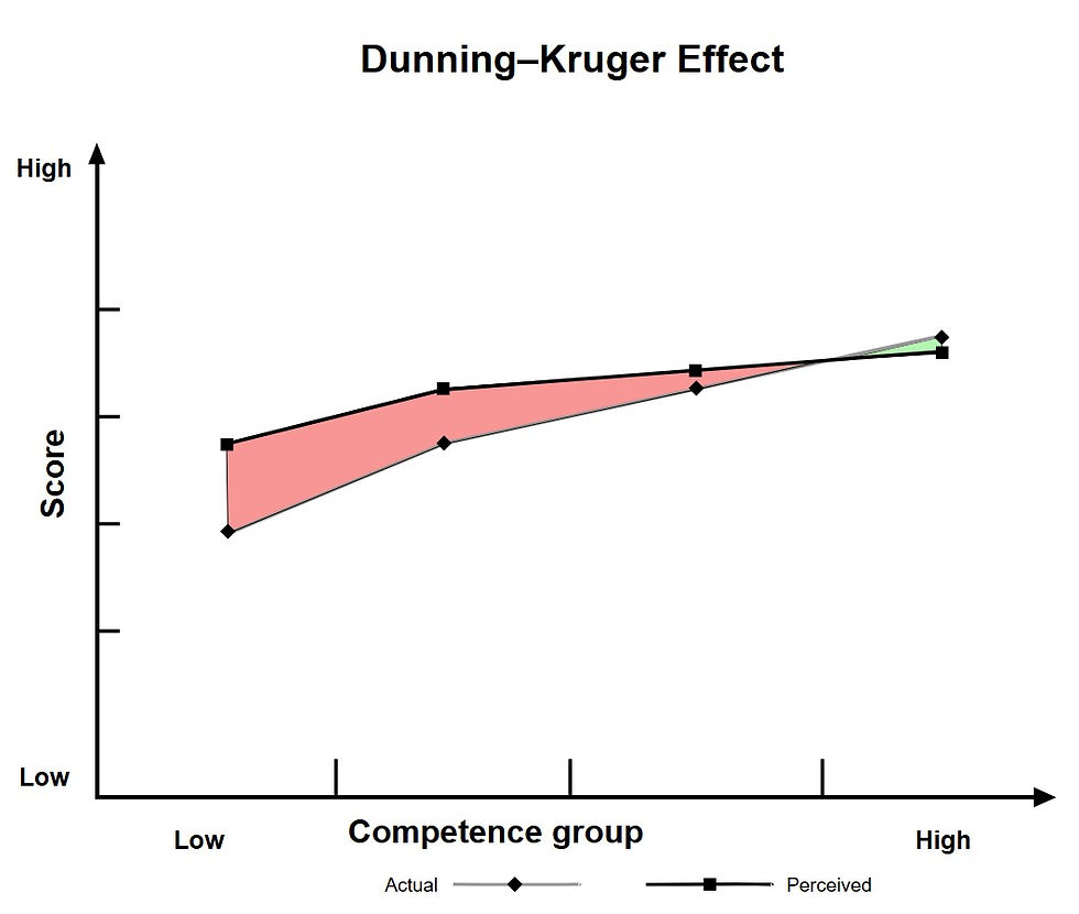
Education can be reassuring, but as it relates to confidence, it can be a bit dangerous. As Neil deGrasse Tyson has paraphrased behavior related to the Dunning–Kruger effect,
“One of the great challenges in this world is knowing enough about a subject to think you're right, but not enough about the subject to know you're wrong.”
I’ve been wrong about a lot, for a very long time, and the head scratching isn’t over. I feel armed enough with information to deal with the average epistemically overconfident individual who writes marketing copy, or the self-aggrandizing ‘guru’ spouting half-baked pseudo-scientific technical explanations. But as far as doing my own evaluation of a product, I have only two reliable components to combine; 1) Try it out, in the specific use context, and if it’s good enough so that I don’t notice any problems, good enough. Or, 2) trust an actual expert.
Figuring out who’s actually an expert deserving your trust versus who’s spinning dreams based on what they think you want to hear, that’s still a lot of work, rife with uncertainty. Most all of them are deep in the industry, and one way or another selling something, because to gain the required experience, they need to do this for a living, and if they’re still doing it for a living, they’ve got to eat like you and me.


Comments